I have seen many posts over the years on over-the-air (OTA) DTV forums where there is confusion over the signal strength of a station and the signal quality. This page will attempt to explain where these are the similar and where they are different. The use and selection of preamps is also covered.
I think it is necessary to cover the concept of Noise Floor in DTV because this number is often used with no explanation of what it is or where it comes from. Noise Floor generally refers to the total thermal noise in a fixed bandwidth. This is important because in practice no signal can be detected below the noise floor.
In DTV the noise floor is said to be -106 dBm and more accurately -106.2 dBm. In a perfect world the ATSC signal needs to be 15.2 dB above the noise floor to produce an error-free picture and audio. In our perfect world then the ATSC signal would need to be -91 dBm or greater. We'll explore in a bit how the world is not perfect. First though, where does -106 dBm come from?
To skip the math, go to Bottom Line below. There is a formula used to calculate thermal noise in a given bandwidth.
Noise=kTB
k=Boltzman's Constant = 1.38E-23
T=Temperature in degrees Kelvin
B=Bandwidth in Hertz
Using a room temperature of 293K (68F) and 1 Hz bandwidth we get:
Noise=4.04E-21
This is a linear number that needs to be converted to dB.
Noise=10*Log(4.04E-21)= -203.9 dBw/Hz (dB referenced to 1 watt)
More commonly we see this number in dBm (dB referenced to 1 millwatt):
Noise=-203.9dBw + 30dB = -173.9 dBm (often rounded to -174 dBm/Hz for convenience)
In DTV the bandwidth is often specified as 6 MHz since that's the maximum bandwidth allocated to each channel.
The increase in noise in a 6 MHz bandwidth over a 1 Hz bandwidth is:
10*Log(6,000,000)=67.8 dB
The noise in the 6 MHz DTV bandwidth is:
-174 dBm/Hz + 67.8 dB = -106.2 dBm or just -106 dBm.
Bottom Line: Using the formula to calculate noise in a bandwidth and converting to dBm, the Noise Floor in the 6 MHz DTV bandwidth is -106 dBm.
This can never be obtained in the real world since that number assumes a noise figure of 0 dB for the first amplifier in the system. It's a starting point from where other calculations begin.
The highest Signal-to-Noise Ratio (SNR) possible is at the antenna terminals. All amplifiers add noise, raising the noise floor and thus decreasing the SNR compared to what it was at the antenna terminals. The Noise Figure of an amplifier specifies how much noise is added. A properly designed DTV tuner should have a noise figure of 6 DB according to the ATSC specification. There's also another 1 dB allowance for tuner inefficiencies. Such a tuner will raise the noise floor to -99 dBm. Since an SNR of 15.2 dB is required for the DTV to display an error-free picture and clean audio, the minimum signal is roughly -84 dBm. Is there any way to improve this? Yes, a preamp.
Let's examine the role of a preamp. There's a common misconception that preamp gain determines how weak of a signal can be received and that ever more gain will receive ever weaker signals. This is not true and is not the function preamp gain plays. The most important number to receive weak signals is what I call System Noise Figure. This is the preamp noise figure plus the effects of losses that occur after the preamp. This is explained in the following paragrpahs.

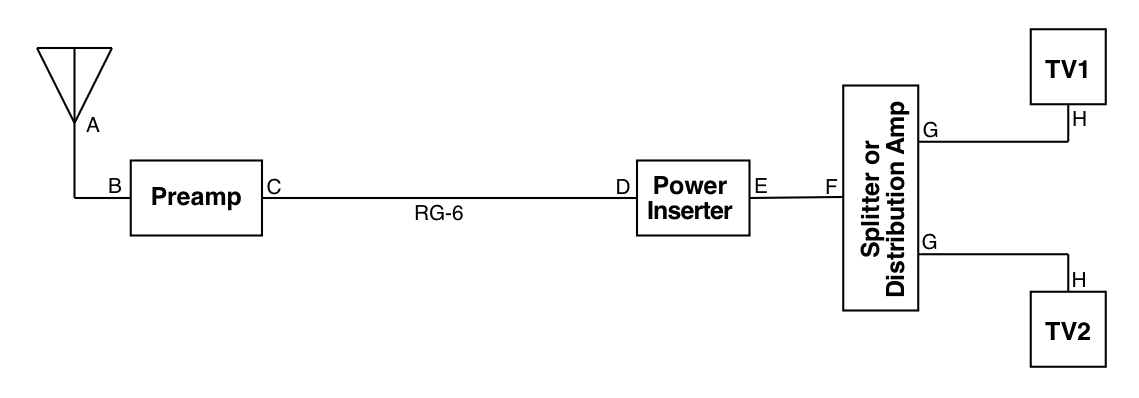
First consider a typical OTA installation shown in the figure above with 100' of RG-6 coax and a 2-way splitter feeding our typical TV with a 6 dB noise figure tuner. The RG-6 typically has a loss of 5 dB at channel 51 and the splitter a loss of 3.5 dB. In this installation the noise floor has been raised 6 dB by the DTV and the signal has been decreased by 8.5 dB from the coax and the splitter loss. Without the preamp, the SNR has been decreased by a total of 14.5 dB from what it was at the antenna terminals. This is irrelevant if the signal at the antenna terminals was 50 dB above the minimum required but very relevant if the signal was 10 dB above the minimum required. The latter would not produce a picture. A properly selected preamp will recover much of that lost SNR.
Note: The difference between the signal and the minimum signal required to decode a picture is called the Noise Margin (NM). This number can be positive or negative.
Suppose we select a good preamp with a noise figure of 2 dB. Disregard the preamp gain for the moment. It is said that the first amplifier in the system sets the noise figure of the system. This is mostly true. A preamp mounted at the antenna mostly eliminates the effects of all the components that follow it but not completely. The gain of the preamp and the amount of loss between the preamp output and the DTV input (C to H above) plus the tuner noise figure reduces the effective noise figure of the preamp. This is the System Noise Figure and there is a formula to calculate it. It calculates what is called Second Stage Noise Figure contribution and adds it to the preamp noise figure. Instead of going through another series of formulas there is a convenient rule of thumb for preamp gain to minimize the affect on noise figure. Let's use the example above where losses plus DTV tuner noise figure were 14.5 dB. When viewed from the antenna terminals, this is the same as saying that the System Noise Figure is 14.5 dB. In order not to degrade the preamp noise figure by more than about 0.5 dB, the gain of the preamp needs to be 6 - 8 dB plus the sum of all the���������������������������������������������������������������������� losses plus tuner noise figure, or 20.5 to 22.5 dB for this example. A 15 dB preamp doesn't have enough gain to overcome the losses after the preamp and will raise the noise figure by a couple of dB. A preamp with more than 23 dB gain will only lower the noise figure by a couple tenths of a dB. With a properly selected preamp, the System Noise Figure in our example can be reduced from 14.5 dB to 2.5 dB. That's a 12 db improvement in weak signal reception over no preamp.
You might think, "Who cares about extra preamp gain even if the noise figure reduction is very small?" There's a problem with this. A DTV tuner has a maximum signal level it can handle without overloading. Any gain above the losses ahead of the tuner raises the signal and the noise floor, effectively reducing the dynamic range of the tuner. In order for the preamp to work, we have to accept losing about 8 dB of the tuner dynamic range. More gain causes more loss of the tuner dynamic range and makes the strong signals so large that they can exceed the maximum signal capability of the tuner. This is how overload occurs. There's no reason to have excessive preamp gain. It's possible to have a situation where the strong signals are so strong without a preamp that they are on the verge of overloading the tuner and the addition of any preamp with the gain selected for minimum noise figure will overload the tuner. In this situation it's best to not use a preamp.
How does a distribution amplifier figure into this? The distribution amp substitutes for the splitter in the figure above and typically has a splitter built into it. If a distribution amp is in the system, then use its noise figure in the calculation instead of the DTV tuner noise figure. The distribution amp becomes the second stage and the DTV the third stage. There is such a thing as Third Stage Noise Figure contribution but it is so small that it can be ignored. The distribution amplifier gain only needs to be enough to cover the losses between the amp and the DTV plus the noise figure of the tuner. There should not be extra gain. Here again, too much gain is detrimental by reducing the dynamic range of signals the DTV can handle and possibly overloading the tuner. Using the numbers from the last calculation, the total losses plus noise figure is now 6 dB + 3 dB + 6-8 dB. The preamp gain needs only to be 15 to 17 dB when using a distribution amp in this example.
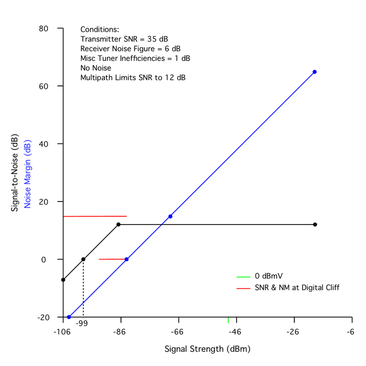
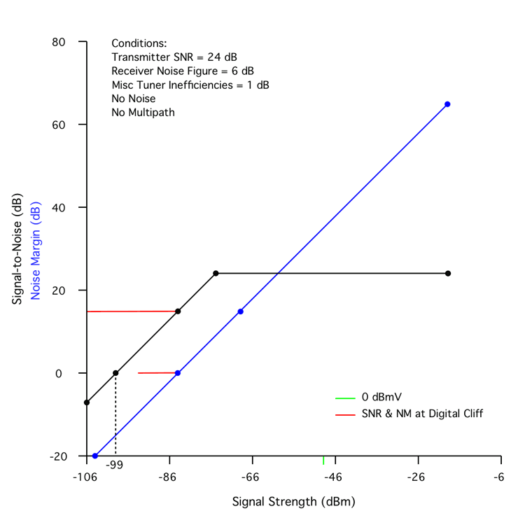
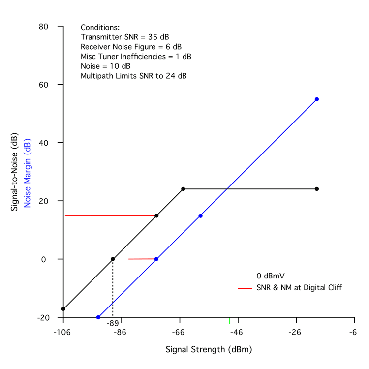
These terms have all been used above but I'll go into detail as to how they relate to each other using some graphs as illustrations. All the following graphs plot SNR and NM in dB on the Y axis and Signal Strength (SS) on the X axis. The green mark is the old analog TV and now obsolete SS of 0 dBmV and is included for reference only.

Figure 1 is an ideal situation. Note the Conditions on the graph. The real tuner described above is used. A SNR of 0 dB occurs at a SS of -99 dBm (the Noise Floor) with a corresponding NM of -15 dB. As the SS rises to -84 dBm, the SNR rises to 15 dB and the NM rises to 0 dB. This is the minimum useable signal. Both lines continue up parallel to each other off the chart.

Figure 2 adds a real world number of 35 dB as the transmitter SNR. The receive SNR can never exceed the transmitter SNR so the receive SNR tops out at 35 dB with an SS of -64 dBm. Note that the NM can continue to increase but there is no corresponding increase in SNR.

Figure 3 adds multipath to the received signal and in this case multipath issues limit the SNR to 24 dB. This is a completely useable signal but an SS of more than -75 dBm does not increase the SNR but NM continues to increase.

Figure 3a shows a severe case of multipath that limits the SNR to 12 dB. This signal is not useable as the SNR is below the minimum of 15 dB and occurs at the low SS of -87 dBm. NM continues to increase but the SNR is stuck at 12 dB.

Figure 4 shows a case of a poorly operating transmitter with an SNR of only 24 dB. This acts just like adding multipath in Figure 3. You can't tell the difference without a specialized ATSC analyzer unless you have prior knowledge of the SNR at your location and it was higher than 24 dB. A local station had this issue for awhile until it got fixed.

Figure 5 adds 10 dB of noise to the received signal. This requires 10 dB more SS to get the same SNR and NM. External noise added to the system acts like a high noise figure amplifier with unity gain. The effective noise figure is just like calculating System Noise Figure. It doesn't take much external noise to ruin the benefits of the preamp when the added noise is much higher than the preamp noise figure. Even external noise that's only equal to the preamp noise figure significantly degrades the System Noise Figure.
In all graphs the SNR and NM track together as the SS goes up until something happens to limit the SNR. It's very common for a strong signal to have a high NM but a lower (or much lower) SNR due to transmitter limitations or multipath issues. NM's above the SNR limit don't help you much but could be sources of overload if the NM is extremely high. Another way to put this is that for weak signals the SS determines the SNR and for stronger signals the SNR is limited by other factors.