This page is a series of photos that I thought would help with the major construction details of the antenna. It is not a step by step construction procedure. I have included tips where I could think of them. Besides the usual array of tools needed for any metal construction project, a tubing cutter is very useful in cutting the tubing to the correct length. I also feel that a drill press is almost a necessity to drill holes straight through the square and round tubing.
There a few things to keep in mind. The antenna is made from two identical halves with one flipped over on top of the other. The surfaces of the two booms that face each each other determine the antenna impedance and they need to be smooth, no screw heads allowed. On each antenna half, the elements alternate sides which performs the criss cross feed function.
First though I've included a parts list of materials for the antenna. The approximate cost of all the material is $100.
| QTY | Description | Source | Part # |
|---|---|---|---|
| 3 | 1/2"x1/2"x72" Square Tube | On-Line Metals | 1/2"x72" Square 6061-T52 |
| 1 | 3/8"x6" Round Tube | On-Line Metals | 3/8"x6" Round Tube 6061-T6 |
| 5 | 1/4"x72" Round Tube | On-Line Metals | 1/4"x72" Round Tube 6061-T6 |
| 1 | 6"x12"x1/4" Delrin Sheet | Tap Plastics | |
| 28 | 6/32x3/4" Pan Head Screws | Local Hardware | |
| 14 | 6/32x1" Pan Head Screws | Local Hardware | |
| 40 | 6/32 Lock Nuts (Nylon Insert) | Local Hardware | |
| 4 | Ferrite Beads | Amidon | FB-43-5625 |
| 1 | U-Bolt and Clamp - 1 1/2" | Summit Source | Aska U-CLAMP |
| 2 | U-Bolt and Clamp - 2" (Alternate) | DX Engineering | DXE-SSVC-2P |
| 1 | F Connector Panel Mount | Pasternack | PE44330 |

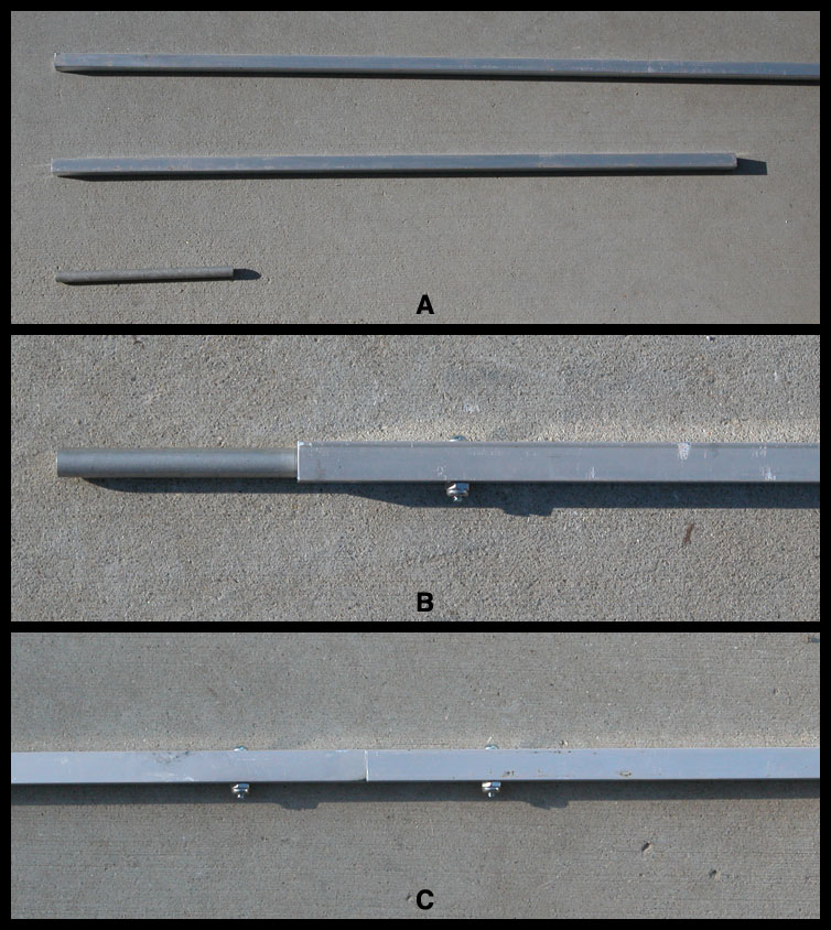
Shipping costs are extremely high for a single 9' length of 1/2" square tubing so I had to splice a 3' piece onto a 6' piece. Figure 1 above shows how I spliced the two pieces together using a 3/8" x 6" tube. The two screws are 6/32 x 3/4". Fortunately the splice occurs between two elements when placed at the front of the antenna.
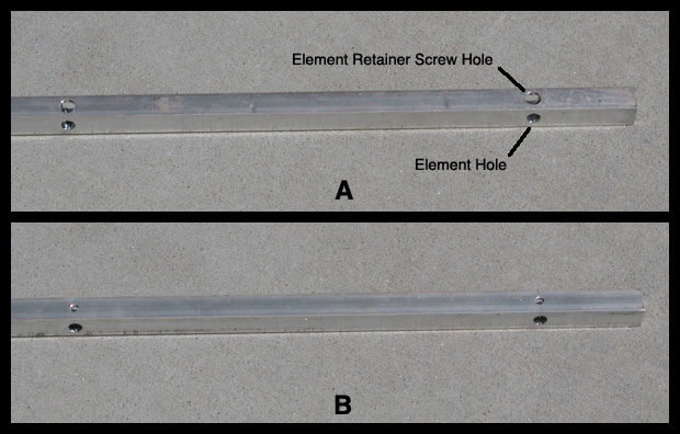
Figure 2 shows some holes drilled for the elements and element fastening screws. I started 2" from the end of the boom. Make sure to drill the holes for the elements on the side parallel to the screws used to make the splice. I used a letter "F" drill for the element holes which is slightly larger than 1/4". You can't get the elements through the holes if you use a 1/4" bit. On the boom surface perpendicular to the element holes, drill a 6/32 body hole through the boom. On the side of the boom that's going to face the other boom half, enlarge the 6/32 hole so that the 6/32 screw head will pass through it. Don't drill through the opposite wall. Using the elements spacing in the table, drill the 10 sets of holes in each boom half.
It would be a good idea at this time to drill the holes for the delrin spacers and the delrin boom to mast plate. See Figure 5 for their locations. The exact locations are not critical. These holes are parallel to the elements holes.
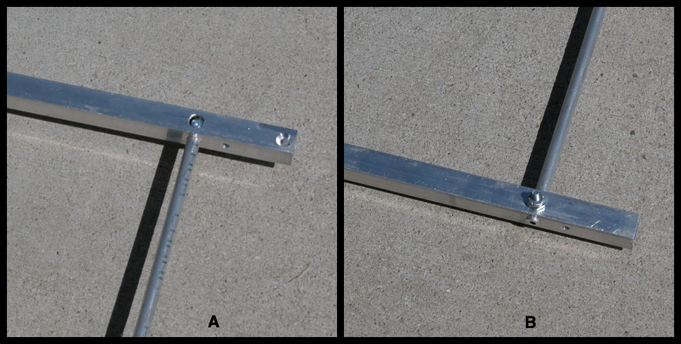
Figure 3 shows how an element is mounted to a boom half. First the elements have to be cut. The element length in the table is the tip to tip length. Because of the way the elements are mounted, there is some overlap inside the boom. The overlap is 5/16" allowing for 1/16" to extend out of the boom for support. Divide the length of the element by 2 and add 5/16". That is the length of each element half. Cut the elements as closely as possible with a tubing cutter. Drill a 6/32 body hole 5/16" from the tip of each element half. Mount as shown in Figure 3. Figure 3 also shows a 6/32 counter sunk hole for the 6/32 x 1/4" screw. This is the hole to mount the connector bracket. One should be drilled in each element half on the side of the boom that will face the other half. Also see Figure 6.
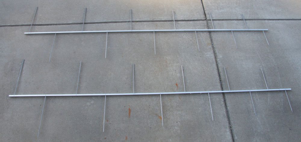
Figure 4 shows the completed halves. Notice they are identical with alternating elements. The sides of the boom that will face each other to form the transmission line are facing up in this image. There are no nuts on this side and the screw heads are below the surface. Note: The image shows the original 10 element version of the antenna.

Figure 5 shows the antenna halves connected together with the 4 delrin pieces and the boom to mast plate. The delrin spacers should be drilled so that the center to center spacing of the boom halves is as close to .812" as possible.
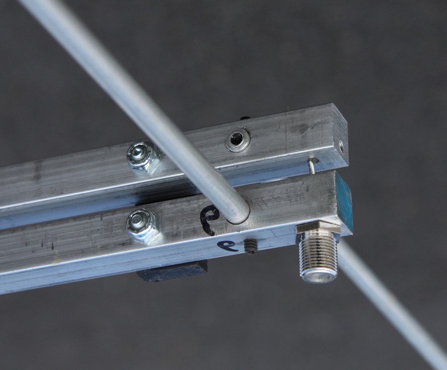
Figure 6 is a close-up view of the F connector on the lower half of the boom. This image shows a solid 1/2" boom and not a tube. This material can be used but it is heavier and set screws hold the elements in place instead of the method shown above. The F connector is 3/8"x32. This requires a 3/8"x32 tap and the tap drill bit size is 11/32". The center conductor is secured as shown to upper boom with a 6/32 set screw in the end of the boom. Holes are visible.
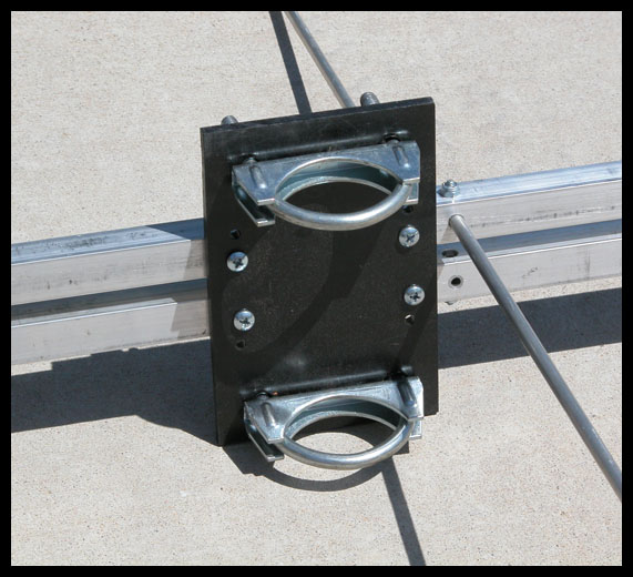
Figure 7 is a photo of the boom to mast clamp on the prototype LP that was mounted on a 2" vertical mast. Use the smaller U-Bolts in the parts table above for 1-1/4" masts.
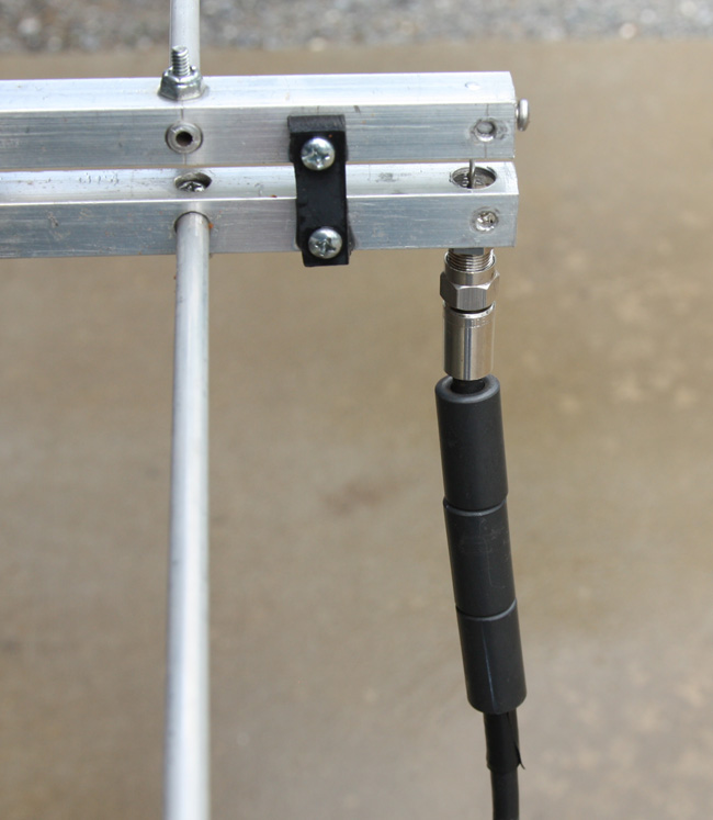
Figure 8 is a photo of the balun. It is simply 4 ferrite beads slipped over a length of RG-6 with a piece of black tape wound around the coax to keep the beads in place. The idea behind this is that a non impedance transforming balun can be made by keeping the RF currents from flowing on the outside of the coax. The beads act like an RF choke. I just followed the example in the ARRL Antenna Book as I have no way to test the impedance of the balun. You must use RG-6 as Quad Shield is too big in diameter for the beads to slip over.
This image shows the F connector mounted on the square tube. In order for the center conductor to make contact as it does with the solid 1/2" upper boom, a 3/8"x1" solid aluminum rod is placed in the end of the boom. It is held in place with a 6/32x1/4" screw. The end is drilled and tapped for a 6/32 set screw. Installation of the F connector is the last step.
The antenna is ready to go. Next I performed some tests.